Last month a friend gave me two old pairs of field glasses. One set was US Navy issue, which has the old-school build quality of a tank, and produces a bright, sharp image. The second pair was cheap and damaged. I’ve considered what to do with it for a while, and finally decided to tear it apart, and use the optical elements inside for educational, research and entertainment purposes. To that end I needed an adjustable optical platform, and while I have plans to make an optical table, for now I wanted to make a simple stack. Here’s how I did it.
The base – I had an old aluminum base plate used on Sutter’s “LS” lamp series. We sometimes discard these bases during installs, so I managed to save this base from the scrap heap. I also snagged one of the support rods. This gave me a post with which to mount optics.
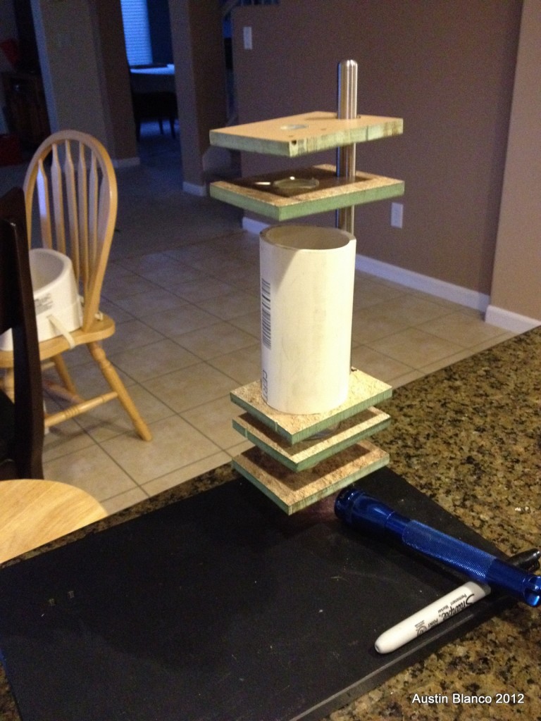
Next I needed something to hold the optics in place. I considered using band clamps, or other methods, but settled on making custom-cut holes that could accept the elements. If you want to do a similar project, you could use drill bits, a scroll saw, or even files to shape out the holes. I was itching to use my DIY CNC machine for something useful, so I employed it to cut the holes for me. I made a set of square blanks, and drilled a single alignment hole in each square. By using this hole as a center, I was able to make each different lens holder have a coaxial alignment, so that the lenses would stack up correctly.
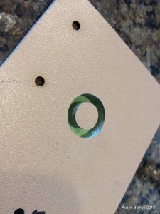
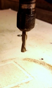
I’ve cut MDF (always wear a respirator when cutting MDF!) before, but have never had a good end mill for the job, so I finally made one by cutting one of my routing bits in half and sharpening the endpoints. The new bit chewed through the MDF with ease. To be extra careful I stepped my cuts at 0.050″ per route at a speed of 2ipm. This is a gentle/slow setup, but I wanted to make sure the parts came out well, and I didn’t want to push the machine for no reason. Finally, because I was cutting down nearly through the material, I set things up to leave a 0.010″ thick layer at the base of each cut. This way when the operation was done, I could simply push out the disk, and not risk cutting up my table on the machine. This process worked really well. Below is a video showing how easy it is to pop out the last layer.
httpv://youtu.be/2j5PQggML94
Here’s a video of the machine cutting out one of the holes. I’ve really been enjoying using the simple python scripts available at emc2’s website. They are handy for simple 2-d jobs.
httpv://youtu.be/-TkGZM2i8_Y
With the holes all cut, I enlarged the alignment holes in each plate so that the plates would slip over the vertical rod I had. They fit snugly and allowed me to adjust the focus of each element as needed.
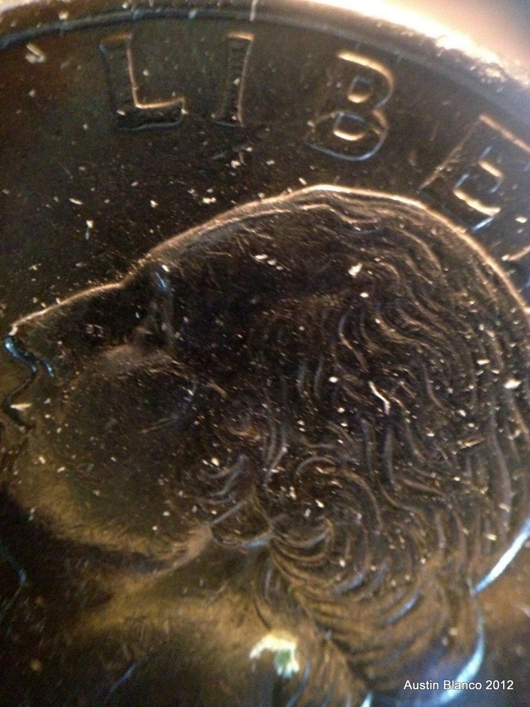
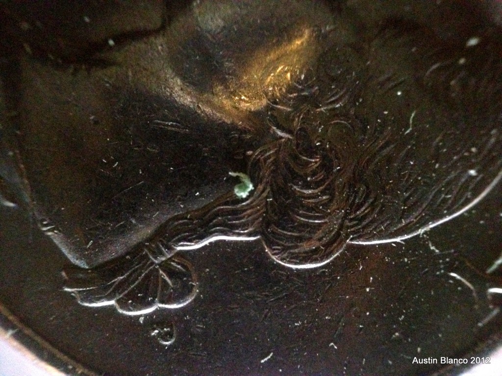
After spending a few minutes playing with the system I was able to set up optic trains providing magnification ranges from 10x to about 40x. The higher mag configurations didn’t look great, but here are some images I acquired using my iphone through the setup.
This was a fun project that only took about two hours to complete. Once I settle on an optimal configuration for these elements, I’ll post on it!
-Austin
