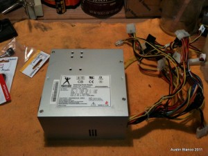
So I got around to making a personal lab power supply from an ATX power supply from an old computer. Who doesn’t have a few old PC’s laying around, right? So after pulling the PS, here were the steps to getting things working:
Things you’ll need before getting started:
- ATX power supply that works.
- Banana receptacles (4)
- SPST Toggle Switch (optional)
- LED with resistor for 5v power.
- Electric drill and bit assortment or a drill press.
- Wire cutters/strippers
- Screw Drivers
- Multimeter
Important Info (Read before you start)
- First off, computer power supply capacitors carry a LOT of juice. Once you remove the cover of this thing DO NOT touch any exposed component, regardless of how long the PSU has been unplugged.
- Next – wire info:
- Green = Power On Signal (needs to be connected directly to ground for PSU to operate or connected to a switch that is connected to ground)
- Orange = 3.3v+
- Red = 5v+
- Yellow = 12v+
- Black = Ground
- There are other voltages but I didn’t use them – google “ATX PSU instructable” if you’re interested in using more
***This should be obvious, but all work should be done with the unit UNPLUGGED.
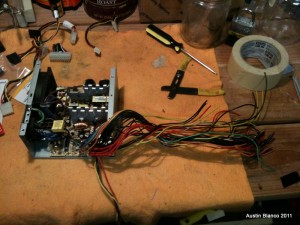
- 1. Get your PS onto a nice clean workspace where you can stretch it’s wires out.
- Cut off the connectors of all of the leads running out of the PSU. Don’t worry about the mess, we’ll clean it up in a moment.
- Remove the cover of the PSU. Mine had 4 screws holding it down.
- Locate the Green wire. This is the “Turn on Button” lead that is normally used to activate the PS when you press the power button on your computer. More on this later.
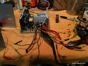
- Bundle the colored wires into separate groups, black, orange, red and yellow. Strip each wire end.
- You can cut all other wires except for the Yellow, Orange, Green, Red and Black lines.
- For each group of wires, twist as many of one color together as you can, and jam a circular crimp-connector on top of the twisted wires, then crimp the connector down. ***Leave ONE of the black lines available and free.
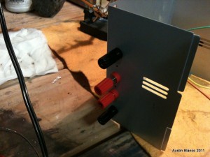
- Now it’s time to drill some holes. Find a suitable location on your PSU cover, where you can install the 4 banana receptacles. Keep in mind we don’t want any leads touching things on the PSU board once the cover is installed! Drill out your 4 holes on the cover.
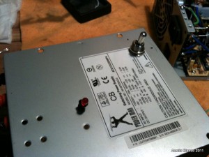
- For control of on-off, you can use the master switch installed on the PSU (if yours has one, most do) or you can add a switch. I had one handy so I added one, along with an LED indicator light to show me the box is on. Instead of a fancy light you could just look at the fan on the PSU, if it’s spinning, it’s on.
- If you opt for a switch, drill a hole for that at this time.
- Install the 4 banana receptacles. I couldn’t find nice color coded ones, so I went for 2 black and 2 red, and just marked with a sharpie what each plug was for.
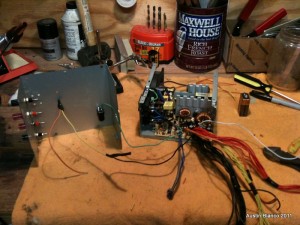
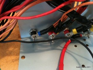
Hardware Installed into cover, note the switch and LED leads. - Install the power-on switch if you are using one.
- Install your LED power indicator if you are using one.
- For the power switch (if applicable) connect the extra ground wire you had available from step seven to one side of the switch, and on the other side connect the green wire.
- If you are not using a power switch, simply connect the green wire to the ground line from step seven and solder or use a twist-on cap to secure.
- Run your ground lead to an appropriate resistor for your LED, and wire the LED up. I used one of the 5v (red) lines to positive side power my LED.
- Hook up your four crimp connectors to the banana receptacles on your cover.
- Before assembly, test the PSU. Be EXTREMELY CAREFUL not to touch anything inside the case. Just check the banana connections for the appropriate voltage.
- If everything works, button up the cover, making sure to not touch ANY COMPONENTS inside of the PSU board, and making sure your wire bundles don’t hit the PSU fan.
- Use whatever method seems best to indicate the off/on switch positions, and most importantly the banana receptacle values.
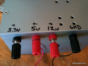
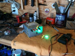
I had a great time making this PSU. It took about an hour, and for a small investment of time and spare parts yielded me a very capable PSU, that I’ve already relied upon several times during other development projects. Were I to make another one, the only thing I’d change is to leave one of the old-school 4 pin power plugs untouched. For one of my projects I needed to confirm that a hard drive was actually causing a power supply to fail. In that case I had to cut off a 4-pin PC power connector and wire the leads up to my PSU to test. Had I just left that 4 pin connector on the PSU, I’d have saved a bit of time.
Comments
3 responses to “Lab PSU from a PC ATX Power Supply”
Nice write up Austin. Spray paint that puppy flat black and use some proper labels and you have a fine finished product. Cool article bro.
Thanks John! I Like your new site design.
[…] the assembled system. To provide the required 5V and 12V power to the cooler and peltier, I used my old reliable ATX Power supply. This assembly low cost components from Amazon and the like. I think the total cost was $27 or […]