2/10-2012 – Followup since completing the My DIY CNC and a review of the device
I’ve had a few months to play with the system, and have learned a whole bunch, as well as discovered how small decisions to build lazy make big changes in the system performance. I’ve also had to make modifications to the system in order to correct for my build flaws, and to correct for what I believe are some inherent design limitations on the platform.
General observations
This project is definitely centered on a “low material cost” vision. What this means is that the cost savings translate into the builder needing to be good at precision machining/drilling. Were I to redesign this, the key item I’d change would be to move from the drill rod guides and bearings, to an I-Beam bearing setup, like the ones provided by IGUS here. Igus also makes a smaller ibeam which could be used for less demanding applications were you to only build this machine for laser cutting or 3d printing work. This type of bearing assembly removes a lot of builder error, at a cost of ~$60 per axis. Considering the labor I’ve invested into building my system, I’d pay the extra to avoid the troubleshooting! Additionally, if you don’t own a drill press (really required for making this machine) then you’ll have to spend ~$120 for one, which equates to 2 axes using a per-manufactured solution.
Modifications
- I made a bearing clamp system that allows me to dynamically control the resistance
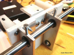
4×32 screws used as a pressure-set adjustment on the igus bearings vs. slop on the guides. I used what tap/screws I had handy (4×32) but I should have used smaller for the thickness of the aluminum L bar. These have helped a lot in allowing me to control the break-in on the system.
- The bearing rods will pull out of the holes they are mounted in. I found this to be true on both the Z and X axes. I addressed this by drilling the base of the Z rod block only partially, so the rods can’t pop out of the bottom.
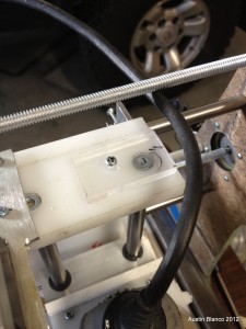
Modifications used to keep the Z axis bearing rods in place On the top side my Z mount partially stopped the left rod from escaping. On the right side I cut a piece of plexi and used it to block the bar from escaping.
- The X motor decided to generate a bit of push-pull drift. This may have been because of binding on the X axis, or because at some point I didn’t power the motor correctly, but in any case the drive shaft would slip to one side when the motor began turning. This translated into about 1/4″ of backlash. I solved this by adding two nuts and a washer to the opposite side of the leadscrew. This prevented the shaft from moving.
- The Z motor coupling
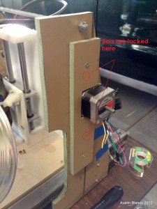
Note the extra MBF layer used to keep the X axis rods in place kept slipping off of the z motor shaft. I addressed this by first using zip ties as recommended by the designer of the system. I later found that the zip ties weren’t tight enough, so I replaced them with a band clamp and have had no further issues.
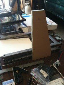
- I added a top clamp bar (seen at right) made from extra 1/4×20 all-thread, which I’ve used to keep the gantry uprights from spreading/contracting during milling operations
- As many others have found, the bearing rods will slip if not secured into the gantry uprights. Even after I added the blocks used to lock my rods in place, I found that any small amount of motion on the part of the rods transmitted into a lot of motion at the tip on the milling bit. Adding a thin layer of tape to the bars before assembly remove this play.
Other Extras
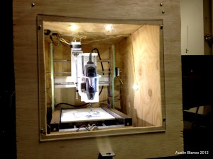
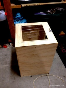
The dremel tool can be quote loud! I decided to add an enclosure to the system in order to run the machine while my kids were asleep in the rooms above the garage. My wife also appreciated the reduction in racket emitting from the garage! I included some nifty high output LED’s a friend gave me (Thanks Gary!) which has really made watching the machine work a pleasurable experience. Before it was loud and chips were flying everywhere. Now the chaos is contained in a nice small box.
Performance
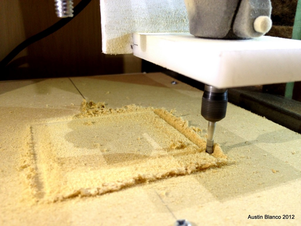
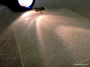
After making all of these mods, I’m approaching the 100th of an inch field in resolution. Not sure yet if it’s down to 1/1000 yet. I’ve got some more testing to do, but here is how nice and smooth my track milling bed looked after milling it out. No ridges or chunks is a good thing!
I’ve so far been able to do some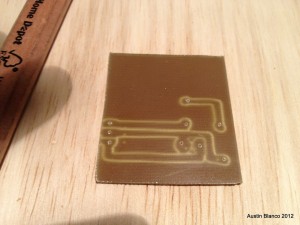 coarse isolation track milling, and some plexi work. I’ve also done text engraving on aluminum, and hope to be taking on more advanced projects once I’ve fully characterized the machine. I would highly encourage anyone who has a desire to learn about motion control, robotics or mechanical engineering to give this product a shot. It’s a relatively small up front investment, and I can’t believe how much I’ve learned by having to work through various small challenges. overall I think this would make an excellent youth, hobbyist or school project to work on. Furthermore, there’s nothing like being able to manufacture parts that you envision, right in your own home!
-Austin
11/4/2011 – SUCCESS!!!
So I FINALLY got the CNC machine done. This was a massive learning experience. Everything from learning stepping motor control, to the rigorous demands of precision machining, has given me a new appreciation for the motorized systems we use on microscopes.
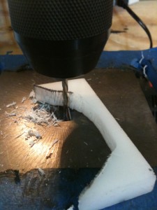
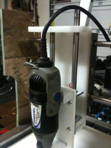
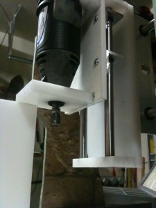
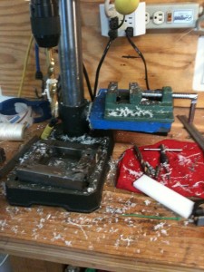
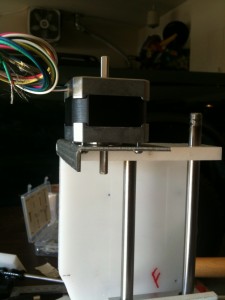
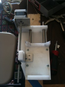
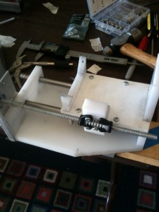
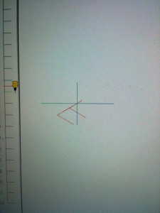
I’ve milled some basic shapes into PFTE, and am planning on aluminum soon. Ultimate applications for this system will be rapid prototyping of various parts for work, some home projects, and who knows what else? Probably I’ll use it to make more tools, like a lathe. Anyways, here are a bunch of pics of the last build days…
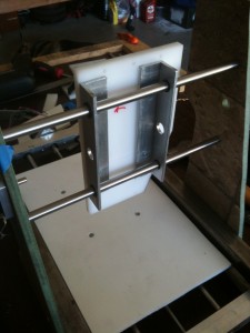
Making the parts for the z carriage and getting everything aligned and working was by far the toughest part of the project for me.
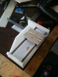
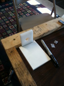
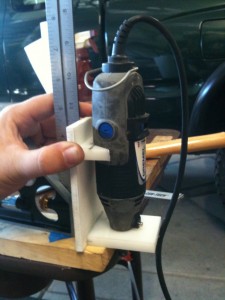
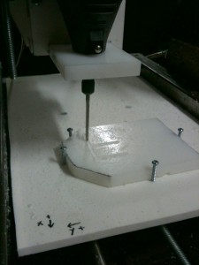
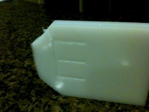
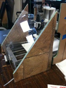
Here’s a video of the system working – (Warning, video is loud, so turn down the speakers)
httpv://www.youtube.com/watch?v=H-otpFe_Mtk
So – sometime in the near future I’ll tighten up things, remake the Dremel mount, and learn a whole lot more about CAD/CAM. The satisfaction of seeing this project to completion is hard to describe. I’m happy with the accomplishment, but at the same time have learned how much I don’t know!
-Austin
10/17/2011 Got a whole bunch more work done on the CNC project. I FINALLY got the X table mounted and working! Here’s a video of the progress. I’ll report more soon I’ve added pics and explanations below:
httpv://www.youtube.com/watch?v=fi-CbM8Ge8Q
What I was quite worried about was the co-alignment of all the holes for each guide rod. If all 4 of the connections to the guide rod aren’t centered or square, you’ll see any number of problems. Binding, non-square cuts and so forth. I am ~75% confident things are working on my system, as the sub-frame guides maintain the same distance from one end of the travel to the other.
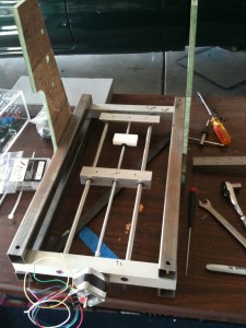
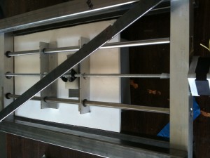
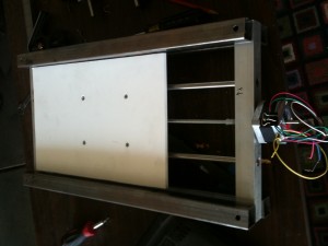
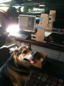
So next steps are the Y and Z assembly tables. I’ve begun fabbing parts for this, and will update once I have them in process.
-Austin
9/24/2011 Well I’ve been steadily chipping away at this project, but not documenting it as rapidly as I had hoped. Duty calls (both foreign and domestic :-)) I’m afraid! So – as I noted earlier due to my crap manufacturing ability and the poor quality of my steel tubes, I was convinced my rails wouldn’t track smoothly. I’m pleased to announce that they track perfect. They are axially rotated, but this can be fixed simply by shimming the x axis plate to level.
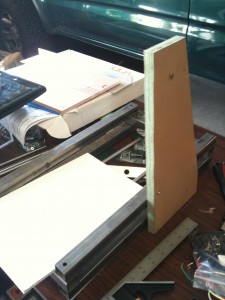
Here’s the overall progress:
Here are the x table sub frames. I used aluminum for this and it’s sooooo much easier to work on compared to steel!
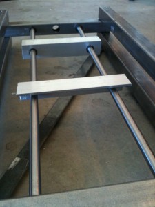
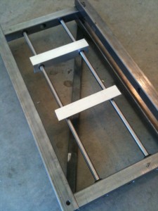
I also cooked up the anti-backlash assemblies for the system. These use an ingenious method of spring pressure to avoid the common issue of having the stepper turn and not actually move the stage. With the spring included, the tension prevents the backlash from presenting itself as an issue. I do expect however that this will require some tweaking to find the balance between smoothness and backlash prevention, and will likely require adjustment over time.
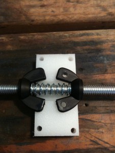
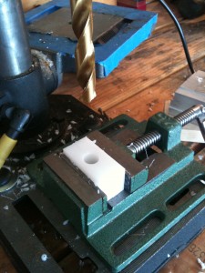
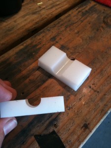
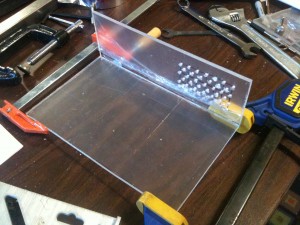
Overall I’m very impressed with the function of the linear bearings from Igus. These little pieces of delrin are finely made, and provide a smooth bearing for operations. Were this a production system I’d obviously use something tougher, but for this system, and for the cost, I could replace these bearings every month for about 3 years before the costs caught up to other options. By then I’ll probably be wanting to expand on this systems’ capabilities in other ways, so the point is moot. Thanks for reading, more to come! -Austin 8/22/2011 Got a lot done in the past few weeks. My 4 connector screw terminals arrived, so I modded the boards to include these: 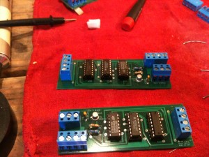 I need a housing for all this stuff (boards, connectors etc), so I’ve been making one out of plexi. The hole pattern was drilled to support airflow. I’m going to have a fan on the far side to make sure the electronics stay nice and cool!
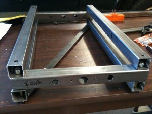
  I finished the base. I think some of my main bearing holes aren’t aligned, which is going to make aligning the system a PITA. I’m realizing maybe this is because I used steel instead of softer aluminum. The steel has a way of bending even on the press that causes the holes not to be drilled flat into the bars. Worst case I’ll have to remake the base. Now that I’ve done it with steel I’m sure the process will be a lot quicker!
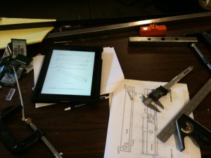
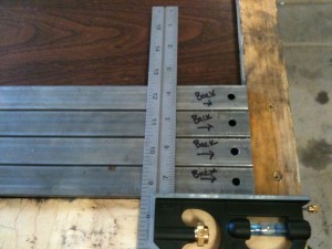
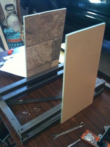
 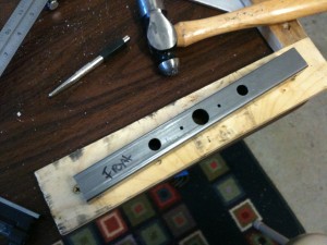 Here are some pics showing some of the final drilled holes, and the assembled base:
-Austin 7/31 – 2011 I’ve made lots of progress over the past week. Had a few late nights working on this stuff, and the usual array of nebulous hiccups. – Completed a scavenge of a 500watt power supply. The newer models require a power draw in order to activate. I ended up soldering up an incandescent bulb for the short term to serve as a draw. – Soldered up the Stepper Motor control modules. These sit between the motor, power supply and computer and translate computer commands into stepping signals for the motors. I was able to test out two of the modules this weekend. Waiting for some more parts to build the third. Here’s a video showing how things work: httpv://www.youtube.com/watch?v=5jrInrByIbA
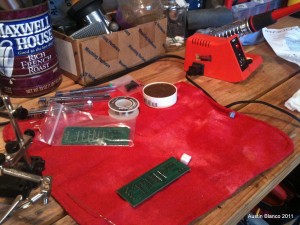
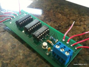
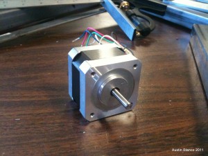
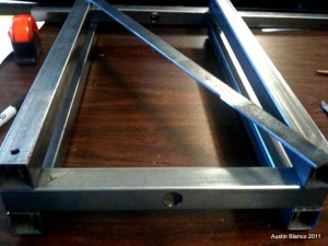
– Completed major cuts on frame. Getting accurate holes in this steel was tough. The steel wanted to roll off axis and the bit needed a big pilot hole.
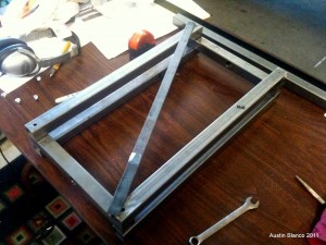
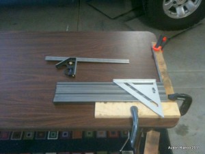
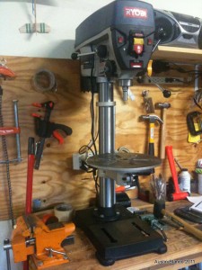
-Austin 7/22-2011 I’m going to document the construction of this CNC machine as I think others will find it interesting and I also hope it will be a reference for others who are building a cnc using Stephen and associates’ mydiycnc plans and manual. So far here’s what I’ve got: – sourced the frame material. In my case I want to mill steel at some point, so I’ve used 1″ steel tube for the frame rails. I’ve cut the tube to the correct sizes and have already mucked up drilling some holes in my first set of horizontal rails 🙂 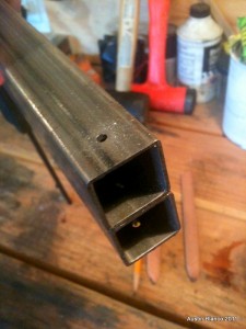 – Misc bolts and screws, whatever I could pick up from the parts list at home depot. – I figured I could use a larger drill press for this project, and it turns out my first cut was bigger than my old press could have handled!
  – I’ve also made a square corner table for working on this project.
 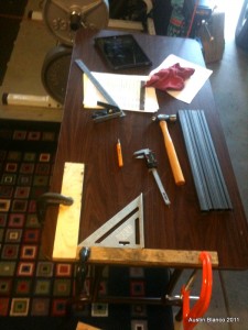 Hoping to get some time to work on things today…. -Austin
Leave a Reply