For some time now I’ve been using 8020 extrusion for quick prototyping of optical assemblies. It’s great for assemblies which require longer focal lengths and larger elements.
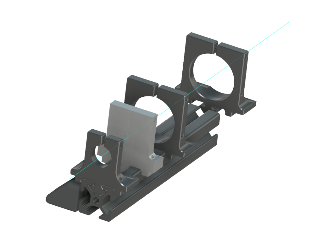
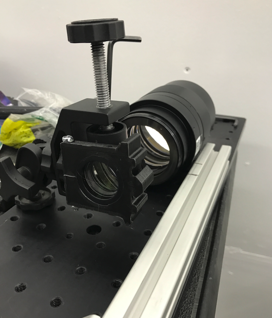
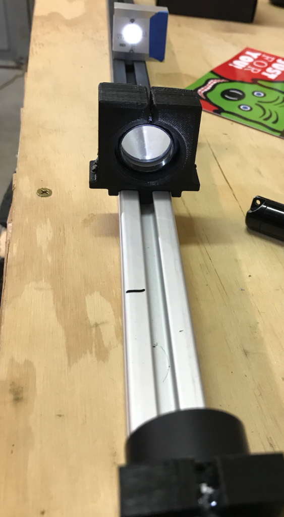
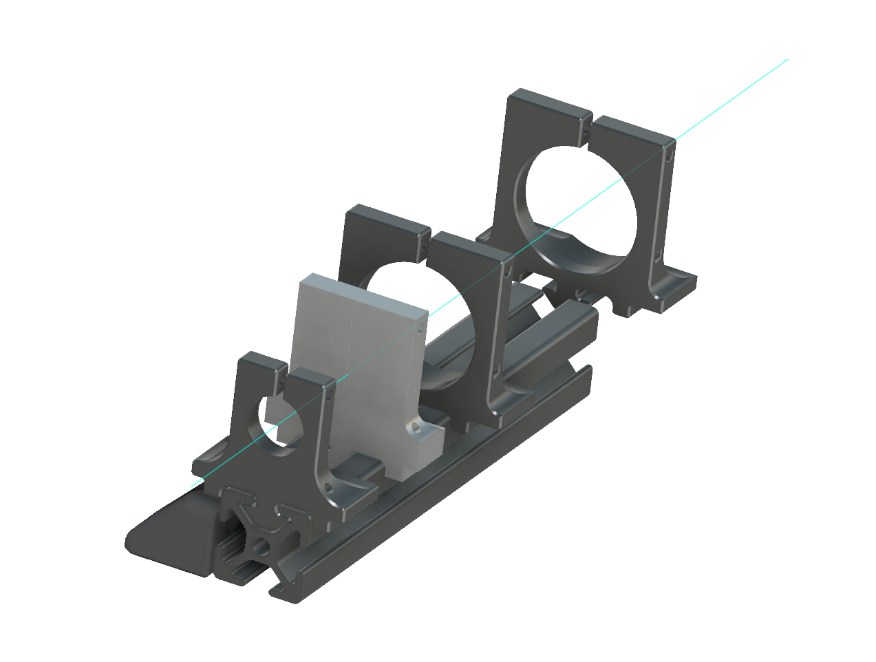
For such systems, the choices are to use a breadboard or table, with posts – and then line everything up, having to worry at minimum about elevation and rotation of each element. Once lined up the parts aren’t quite easily moved around. For my parts, I simply created a negative profile for the “8020” 2525 brand of extrusion, then placed a 32mm circle at the center of this profile with vertical clearance. Likely I should have placed it higher, but for most elements it’s simple to create a clamp, send it to the 3-D printer, stick the element inside and voila, held at an axial center, generally en face, and very easy to slide back and forth.

For complicated systems which may use reflection or episcopic combined paths, additional pieces of extrusion can be cut and aligned to a core axis quite easily, and even attached in 3 rotations (left, right and “up” from the primary optical axis). Extrusion pieces can be ordered pre-cut, or easily cut to length using a hacksaw. Right angle clamps avoid any angular errors caused by bad cuts. Personally I use a mill to face off the ends, but most people don’t have access to a mill.

To make things even easier, it’s nice to be able to mark off critical dimensions on the extrusion with a felt tip pen, which is easily later removed from the anodized surface with IPA.

I’ve added all of the designs I frequently start from, in STEP format. If someone needs another format please let me know and I’ll export one.
The files are hosted on my CAD share on Github Here.
-Austin
